GE IS200BPIIH1A IS200BPIIH1AAA Bridge Power Interface Board
Description
| Manufacture | GE |
| Model | IS200BPIIH1A |
| Ordering information | IS200BPIIH1AAA |
| Catalog | Speedtronic Mark VI |
| Description | GE IS200BPIIH1A IS200BPIIH1AAA Bridge Power Interface Board |
| Origin | United States (US) |
| HS Code | 85389091 |
| Dimension | 16cm*16cm*12cm |
| Weight | 0.8kg |
Details
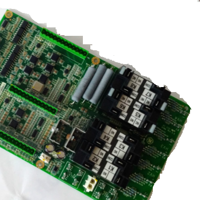
The IS200BPIIH1AAA, from the GE Speedtronic Mark VI series, is a Bridge Power Interface circuit board designed for use in Innovation Series drives.
The IS200BPIIH1AAA is used by the GGXI board to communicate gate command and status signals via RS-422 signals. The RS-422 drivers and receivers use point-to-point signaling that will alarm a bad gate signal if the cable is disconnected. The IS200BPIIH1AAA uses a serial prom ID chip and pull-up resistors. The resulting pull-up signal indicates that all cables are properly connected along the signal path.
The IS200BPIIH1AAA has four connectors on its surface: two mounted in the front faceplate and two on its back edge. The rear connectors are 128-pin backplane connectors. Pin signal maps are available in GEI-100298. The two front connectors are designed to interface with the GGXI board. Each connector, labeled JGATE1 and JGATE2, has 68 pins.
The front faceplate has no other mounted components but is marked with the GE logo, the board number, and with the proper location of the board (slot 6.) Improper seating of the board can damage the component. Do not insert it in the wrong slot. The board has no fuses, user test points, LED indicators, or adjustable hardware.
The IS200BPIIH1A is a Bridge Power Interface Board that is used within the GE Speedtronic Mark VI Series.
The IS200BPIIH1A is used within Innovation Series Drives. It interfaces with IGCT switching devices and provides a number of feedback signals, control signals, and accessibility points for other boards like the Expander Load Source Board (IS200GGXIG) in conjunction with the BICI board.
The BPII board uses RS-422 connectors to communicate gate commands and status signals. It also relays up to 24 gate status feedback signals and gate firing commands between GGXI boards.
The IS200BPIIH1A is designed with two 128-pin backplane connectors that are labeled P1 and P2. The board also has two 68-pin connectors mounted into its front faceplate. These are labeled JGATE1 and JGATE2, and are typically used to interface with GGXI boards. The front faceplate also has two clips to hold the board in place after it is inserted into a rack system and is marked with the GE logo, the board’s identification number, and a warning to “install in slot 6 only.”
Boards that are installed improperly may be damaged or may damage the system.


