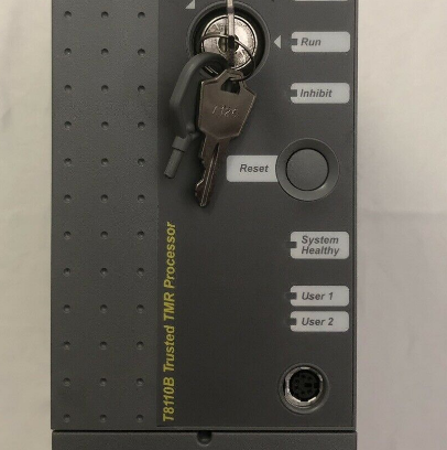
ICS Triplex T8110B Trusted TMR Processor
Description
| Manufacture | ICS Triplex |
| Model | T8110B |
| Ordering information | T8110B |
| Catalog | Trusted TMR System |
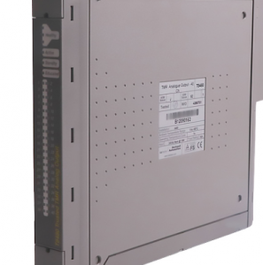
| Description | ICS Triplex T8110B Trusted TMR Processor |
| Origin | United States (US) |
| HS Code | 85389091 |
| Dimension | 16cm*16cm*12cm |
| Weight | 0.8kg |
Details
Trusted TMR Processor Product Overview
The Trusted® Processor is the main processing component in a Trusted System. It is a powerful, user-configurable module providing overall system control and monitoring facilities and processes input and output data received from a variety of analogue and digital Input / Output (I/O) modules across a Trusted TMR Inter-Module Communications Bus. The range of applications for the Trusted TMR Processor vary in integrity level and include fire and gas control, emergency shutdown, monitoring and control, and turbine control.
Features:
• Triple Modular Redundant (TMR), fault tolerant (3-2-0) operation. • Hardware Implemented Fault Tolerant (HIFT) architecture. • Dedicated hardware and software test regimes which provide very fast fault recognition and response times. • Automatic fault handling without nuisance alarming. • Time-stamped fault historian. • Hot replacement (no need to re-load programs). • Full suite of IEC 61131-3 programming languages. • Front panel indicators that show module health and status. • Front panel RS232 serial diagnostics port for system monitoring, configuration and programming. • IRIG-B002 and 122 time synchronisation signals (available on T8110B only). • Active and Standby processor fault and failure contacts. • Two RS422 / 485 configurable 2 or 4 wire connections (available on T8110B only). • One RS485 2 wire connection (available on T8110B only). • TϋV Certified IEC 61508 SIL 3.
1.1. Overview
The Trusted TMR Processor is a fault tolerant design based on a Triple Modular Redundant (TMR) architecture operating in a lock-step configuration. Figure 1 shows, in simplified terms, the basic structure of the Trusted TMR Processor module. The module contains three Processor fault containment regions (FCR), each containing a Motorola Power PC series Processor and its associated memory (EPROM, DRAM, Flash ROM, and NVRAM), memory mapped I/O, voter and glue logic circuits. Each Processor FCR has voted two-out-of-three (2oo3) read access to the other two Processor’s FCR memory systems to eliminate divergent operation. The module’s three Processors store and execute the application program, scan and update the I/O modules and detect system faults. Each Processor executes the application program independently, but in lock-step synchronisation with the other two. Should one of the Processors diverge, additional mechanisms allow the failed Processor to re-synchronise with the other two. Each Processor has an interface which consists of an input voter, discrepancy detector logic, memory, and an output driver bus interface to the Inter-Module Bus. The output of each Processor is connected by the module connector to a different channel of the triplicated Inter-Module Bus.
3. Application
3.1. Module Configuration The Trusted TMR Processor requires no hardware configuration. Every Trusted System requires a System.INI configuration file. Details of how to design this are given in PD-T8082 (Trusted Toolset Suite). The configuration has a Processor assigned to the left slot of the Processor chassis by default. The System Configurator allows the selection of options on ports, IRIG and system functions. The use of the System Configurator is described in PD-T8082. The options are described below.
3.1.1. Updater Section If Auto Protect Network Variables is selected, this configures the Trusted System to use a reduced Modbus Protocol map. See product description PD-8151B (Trusted Communication Interface Module) for further details. Inter Group Delay equates to the Modbus update cycle. This is the minimum period between successive Modbus update messages sent to each of the Communications Interface Modules. The default value (as shown) is 50 ms which provides a compromise between latency and performance. Adjustment is made in 32 integer ms increments, i.e. a value of 33 will equal 64 ms as will 64.This may be increased or decreased as required, however since only one update message is sent per application scan, and an application scan may often be more than 50 ms, there is little benefit in adjusting this variable.
3.1.2. Security Section The above display is also used to configure a password allowing the user to interrogate a Trusted System using the Windows-based HyperTerminal facility or a similar terminal program. The password is configured by selecting the New Password button and entering the new password twice in the displayed dialogue box.
3.1.3. ICS2000 Section This section only applies to Trusted Systems connected via a Trusted to ICS2000 Interface Adapter to an ICS2000 system. This allows the data sources for the three mimic tables to be selected. Please refer to your Trusted supplier for further information.


