GE DS200TCQAG1B DS200TCQAG1BEC Analog I/O Board
Description
| Manufacture | GE |
| Model | DS200TCQAG1B |
| Ordering information | DS200TCQAG1BEC |
| Catalog | Speedtronic Mark V |
| Description | GE DS200TCQAG1B DS200TCQAG1BEC Analog I/O Board |
| Origin | United States (US) |
| HS Code | 85389091 |
| Dimension | 16cm*16cm*12cm |
| Weight | 0.8kg |
Details
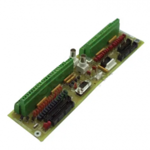
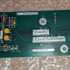
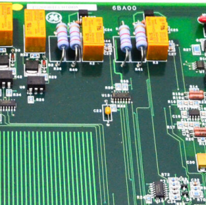
The GE RST Analog I/O Board DS200TCQAG1B contains four 34-pin connectors, two 40-pin connector, and six jumpers. The board also has 6 LEDs. The GE RST Analog I/O Board DS200TCQAG1B is designed to be installed in the board cabinet in the drive. The board cabinet has racks for the installation of the boards. The boards have screws holes that align with the rack and enable you to use screws to secure the boards.
When you remove the old board, retain the screws and washers that secure the old board and keep them in a safe place for later use when you secure the replacement board. If any of the screws or washers fall into the drive interior, stop what you are doing, locate them, and remove them from the drive. If you start the drive with loose debris it might cause injury due to the high-voltage electric current or the moving parts might became jammed or damaged. It is best practice to use two hands when you remove or install the screws. Use one hand to turn the screwdriver and one hand to hold the screws and washers.
Another consideration is the jumpers on the board. Some of the jumpers are used to configure the board for the user. Other jumpers are not to be changed by the user and are instead used for testing at the factory or are set to enable one configuration. Before you install the replacement board, set the jumpers on the replacement to match the settings on the old board.
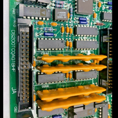
The DS200TCQAG1B General Electric RST Analog I/O Board contains two pairs of 34-pin connectors, a pair of 40-pin connectors and six jumpers along with 6 integrated LED lights that are arranged in two rows with three of them in each row and each are situated to be viewed from the edge of the board. The LEDs provide a status of the health of the board, including the processing activities. This board has an advanced Intel microprocessor and is located in the R, S, and T cores in the Speedtronic MKV panel. When replacing the board, it is best practice to identify and note exactly where the ribbon cables are connected on the board before disconnecting them. All the connectors, jumpers, and LEDs have identifiers printed on the board. By labeling these tags you will find it easier to reattach the cables to their original connections dfuring the installation process.
The replacement board might be a later version of the same board so it is possible that the locations of the connectors has changed. The appearance of the components might also seem different as this is due to updates and modifications completed by the manufacturer. Even so, the different versions of the same model boards are all compatible and when you replace the older version with the newer version you can be certain that the new board will provide the same functionality.