GE DS200TBCAG1AAB Analog I/O Terminal Board
Description
| Manufacture | GE |
| Model | DS200TBCAG1AAB |
| Ordering information | DS200TBCAG1AAB |
| Catalog | Speedtronic Mark V |
| Description | GE DS200TBCAG1AAB Analog I/O Terminal Board |
| Origin | United States (US) |
| HS Code | 85389091 |
| Dimension | 16cm*16cm*12cm |
| Weight | 0.8kg |
Details
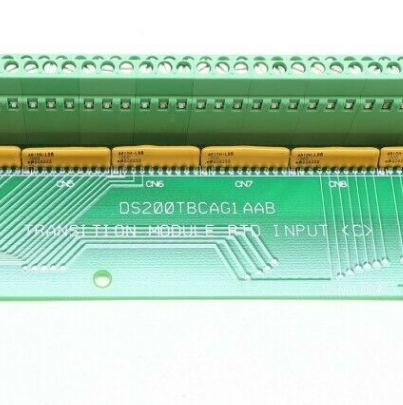
The GE Analog I/O Terminal Board DS200TBCAG1AAB features 2 blocks of 90 signal wire terminals and 2 50-pin connectors.
The replacement of the GE Analog I/O Terminal Board DS200TBCAG1AAB is a straightforward procedure provided you can move the signal wires from the terminal blocks on the old board to the terminal blocks on the replacement board.
Only a qualified servicer can perform this task due to the high energy contained in the drive when it is connected to electrical current. Disconnect the drive from the power source which is installed to meet local and national electrical standards. The drive is connected to a power supply that converts AC power to the DC power used to run the drive.
It is also important to locate the emergency power shut off equipment connected to the drive. In case of an emergency it is important to have at least two individuals working on the replacement. If an emergency situation occurs, help is available to call for emergency assistance or shut off the power using the emergency shutoff device.
First, if possible remove the defective board with the signal wires still attached and place it on a clean and stable surface with an EDS protective surface underneath it. For example, a flat static protective bag. Wear a wrist strap and place the replacement board next to the old board. And one at a time move the signal wires from the old board to the new board.
The DS200TBCAG1AAB GE Analog I/O Terminal Board features 2 blocks of 90 signal wire terminals and 2 50-pin connectors along with one 50-pin connector that is labeled JDD and the other labeled JCC. Attached to ribbon-type cables are 50 pin connectors that require some special consideration before you connect or disconnect them to prevent damage to the ribbon cable.
To disconnect a ribbon cable do not touch the ribbon portion of the cable. Hold the connector portion and remove it from the connector on the board while using your other hand to support the board and keep the board. Each signal is made up of a fews strands of copper wire that might be inadvertently disconnected from the connector. If this happens, it will prevent the board from receiving the signal for processing or possibly prevent the board from transmitting the signal.
There are potentially multiple signal wires connected to the terminals and so it is best practice to designate where to connect each signal wire by labeling each wire with the ID of the terminal before you disconnect it. Doing so will eliminate the opportunity for error that would increase the downtime for the drive.