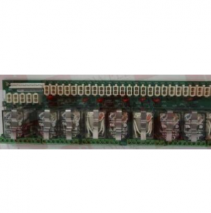
GE DS200DTBCG1AAA Connector Relay Terminal Board
Description
| Manufacture | GE |
| Model | DS200DTBCG1AAA |
| Ordering information | DS200DTBCG1AAA |
| Catalog | Speedtronic Mark V |
| Description | GE DS200DTBCG1AAA Connector Relay Terminal Board |
| Origin | United States (US) |
| HS Code | 85389091 |
| Dimension | 16cm*16cm*12cm |
| Weight | 0.8kg |
Details
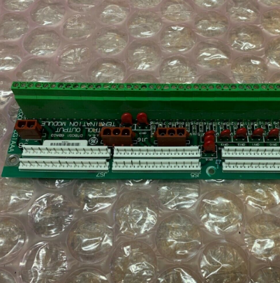
The GE Connector Relay Terminal Board DS200DTBCGIAAA features 2 terminal blocks with terminals for 110 signal wires in each. It also contains 2 3-plug connectors and 1 2-plug connector and 10 jumpers.
When you plan to replace the GE Connector Relay Terminal Board DS200DTBCGIAAA there are several steps to take before you remove the old board. First it is necessary to remove all power from the drive. Keep in mind that multiple sources of power supply electricity to the drive and when you remove power from 1 source you have to remove power from the remaining sources of power. It is best to consult with someone who is familiar with the installation of the drive to understand the various power sources and how best to remove power to the drive. For example, a rectifier converts ac power to dc power and you can disable a rectifier to remove dc power to the drive. This often is accomplished by removing a fuse from the rectifier. If ac power is supplied to the drive, you might use another method to remove power. This might include pulling a switch or removing power by turning off a circuit breaker.
View the board and notice where it is installed in the drive. Plan to install the replacement in the same location. Create a diagram or illustration of where the signal wires are attached to the terminals. Use strips of masking tape to create temporary tags on which you can write down the terminal ID the wire is attached to.
The DS200DTBCG1AAA GE Connector Relay Terminal Board located in the QD or C cores features 2 terminal blocks with terminals for 110 signal wires along with 2 3-wire bayonet connectors, 1 2-wire bayonet connector and 10 jumpers. The input voltage range is 24 VDC to 125 VDC and the berg jumpers can be removed to aid in troubleshooting. Since the board can have 220 signal wires attached to it, it is best practice that you mount it where the signal wires can be properly routed. Due to the risk of interference the signal wires can not be routed near power cables. The reason for this is that the power cables are considered noisy meaning that they radiate signal noise that can interfere with the accuracy of the signals received by the board.
For additional protection, shielded wires can be used to block the interference however, the best solution is to route the power cables separately from the signal wires. If the cables must be routed together, it is best to limit its length by bundling together. The more current a power cable carries the further away the power cable and signal cables should be routed from each other. Ensure that you are routing the signal wires so that they do not interfere with the air flow inside the drive. The reason for this is that the drive is designed so that cool air enters the drive at the bottom of the drive through air vents. The air flows over the heated components and carries away the heat through vents at the top of the drive.