GE DS200DTBBG1ABB Terminal Digital Connector Board
Description
| Manufacture | GE |
| Model | DS200DTBBG1ABB |
| Ordering information | DS200DTBBG1ABB |
| Catalog | Speedtronic Mark V |
| Description | GE DS200DTBBG1ABB Terminal Digital Connector Board |
| Origin | United States (US) |
| HS Code | 85389091 |
| Dimension | 16cm*16cm*12cm |
| Weight | 0.8kg |
Details
Product Description
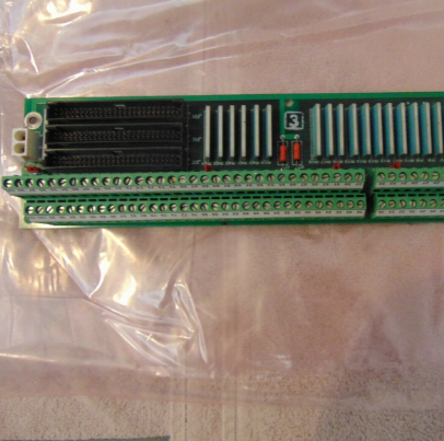
The GE Terminal Digital Connector Board DS200DTBBGIABB features 2 terminal blocks with terminals for 95 signal wires in each. It also contains 3 50-pin connectors. The IDs for the 40-pin connectors are JFF, JFG, and JFH. It also is populated with bayonet connectors and 5 jumpers.
The board is 3 inches in height and 11.5 inches in length. It has 1 hole in each corner for the installer to attach the board to the board rack in the interior of the drive. The drive has multiple positions that can accept the installation of the board. However, it is best practice to install the board in the same position as the old board it is replacing. This is because of the large number of signal wires and ribbon cables attached to it. Cable routing is very important. If the cables are not routed properly interference can result and also the cooling of the drive interior can be negatively affected. The drive interior has many power cables and signal wires and ribbon cables. The power cables if routed too near the signal wires can interfere with the signals. This might result in inaccurate signals being transmitted and received by the board. The solution is to route the power cables as far as possible from the signal wires.
The other problem that can result from improper cable routing is reduced air flow within the drive. This can occur if bundles of cables block the flow of air in front of air vents or around components that generate heat.
The DS200DTBBG1ABB GE Terminal Digital Connector Board features 2 terminal blocks with terminals for 95 signal wires and 3 50-pin connectors, bayonet connectors and 5 jumpers. IDs for the 40-pin connectors are JFF, JFG, and JFH. Since this board has 3 40-pin connectors it is best practice to record what 40-pin ribbon cable is connected to which of the connectors. If you have connected the ribbon cables to the wrong connectors it will require you to bring down the drive move the ribbon cables to the right connectors and restart the drive resulting in an outage and uneccessary downtime.
Create a diagram or label connectors to prevent delay in operations. This board has the ability to attach a maximum of 110 signal wires to the terminal blocks however this will be difficult to manage without documenting where the signal wires are connected. One terminal block is assigned TB1 as the ID and the other terminal block is assigned TB2 as the ID with separate terminals numbered in sequence on each terminal block. To identify a specific terminal you can use the terminal block ID and the number assign to the terminal. For example, TB1 90 and TB2 48. TB1 90 is terminal 90 on terminal block 1. TB2 48 is terminal 48 on terminal block 2.